K-Cell 2.0
The K-Cell allows reliable and easy deployment of LoRaWAN sensors to any location on the planet. The system acts as a store and forward solution by hosting the LoRaWAN application at the edge and forwarding data onward via the CONNECT cloud system to your own servers. The K-Cell supports multiple backhauls and intelligent switching between satellite and cellular connectivity provide exceptional resilience and reach. This makes for secure, reliable network connectivity, with minimal chances of downtime and data loss.
The K-Cell can be deployed in off-grid, offshore and remote locations without issue.
K-Cell Specification
Physical Specifications
| Property | Specification |
|---|---|
| Enclosure dimensions | 330 mm x 230 mm x 113 mm 13.01" x 9.07" x 4.43" |
| Mass | 9.2 Kg |
| Mounting | Wall & pole |
| Battery capacity | 29Ah |
| IP ratings | IP68, UL50E, Type 6P |
| Certifications | CE, FCC, ISED, UKCA, RCM, RSM |
Power input
| Type | Voltage Range | Current spec | Power |
|---|---|---|---|
| AC 50/60Hz | 110-240V | 1.8A/115V 1A/230V | 207/230W |
| DC | 12-24V | Inrush/Max 6A/12V 3A/24V |
72W |
| Nominal 4.6A/12V 2.3A/24V |
55.2W |
Power Output
| Type | Voltage Range | Current spec |
|---|---|---|
| DC | 24V | 3.3A |
Device communications
| Radio Protocol | Frequency | Range |
|---|---|---|
| LoRaWAN | 868\915Mhz | < 15 Km |
Note that LoRaWAN frequency is region dependant. The appropriate K-Cell is required for your region(s) of use.
Backhauls
| Primary Cellular | NB-IoT/Cat-M |
| Secondary Cellular | EGPRS |
| Primary satellite | Geostationary |
| Secondary satellite | Low-Earth Orbit (LEO) |
Off Grid solutions
Our off-grid solutions are customised to match the environment and customer usage. Typical examples include solar, methanol fuel cells, wind generators, or a combination of these.
Mounting the K-Cell
Positioning considerations
- Primary consideration should be given to the "K-Cell antenna mounting" section below, as a bad antenna installation is likely to cause a K-Cell to not perform to its full capabilities.
- The K-Cell mounting position must be less than 5m cable run from the antenna mounting position, as this is the length of the antenna cables. These cannot be extended.
- The K-Cell must be mounted with at least 300mm clearance from any obstructions below it, for cable and antenna connections.
- The supplied power cables are 5m, but these can be extended (see caveats in cables information).
Pole mount
Jubilee clamps (supplied)
The K-Cell is supplied with jubilee clamps that will enable it to be mounted to a pole with a diameter of up to 150mm. If a larger diameter pole mounting is required, larger diameter clamps should be sourced locally, with a thickness of less than 20mm.


- Starting with the upper bracket, thread the jubilee clip through one of the inner slots on the front of the K-Cells mounting bracket. If a larger clamp and pole diameter greater than 120mm is being used, the wider slots should be used to give the K-Cell better grip on the pole.
- Wrap the clamp strap around the pole, and thread back through the opposite slot.
- Thread the end into the opening of the clamping mechanism and tighten until the K-Cell is secure.
- Repeat to clamp the lower bracket to the pole.
U-bolts (not supplied)
The K-Cell can be mounted using U-bolts with thread diameter 5-8mm, and inner spacing between 48-66mm. Penny washers (otherwise known as mudflap washers) are required between the nut and the K-Cell's mounting bracket.
Wall mount

- 4x 6-8mm diameter fixings should be used, one in each corner. These are not supplied.
- Suitable fixings should be procured for securing the 9.5kg k-Cell to the wall material.
K-Cell antenna mounting
The antenna bracket must be mounted within 5m of the K-Cell installation location due to maximum cable lengths.
The installation location is an important factor for the K-Cell to function correctly, due to satellite connectivity of its antennas. The ideal location would have a completely clear view of the sky in the hemisphere above the antennas, but as this is not always possible the following examples should be used to determine the best installation location.
Surrounding obstacles
The puck antenna requires a clear view of the sky in all directions as much as is possible. If there are limitations, then higher priority should be given to the north if above the equator, and the south if below the equator.
In Europe, the Hughes 4500 terminal requires a clear view of the sky to the south, above 20 degrees from horizontal. If there are obstacles to be avoided, a clear view of the sky above 20 degrees from horizontal, towards Equatorial Guinea should be traceable on a map from the position of the antenna.
A satellite finder app with Echostar 21 selected, can be used on a smartphone to confirm clearance of obstacles.
EchoStar Mobile Coverage - EchoStar Mobile
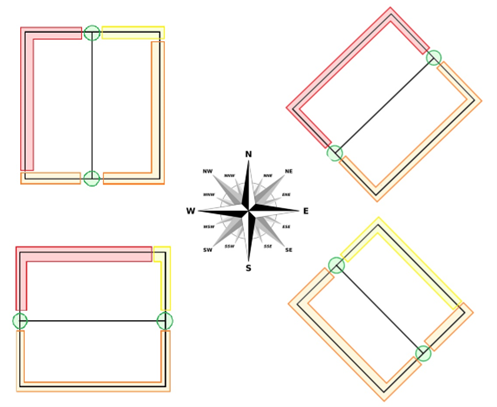
UK pitched roof example
If mounting onto a building with a pitched roof, the optimum position to avoid the roof from blocking the signal is on one of the ends above the apex, so that the antennas clear the top of the roof.
If this is not possible, see the following diagram for examples of the best mounting positions on pitched roofs in different orientations in the west of the UK, where the centre line of each box is the centre of the roof pitch.
Western UK example, where Equatorial Guinea bearing is SSE (south-south-east):

Antenna bracket installation
The Hughes terminal is to be mounted onto the front of the antenna bracket with the socket facing in through the opening, using the provided 4x M5x10mm allen screws.
The cable connector should then be fitted through the opening on to the Hughes terminal and tightened on.
The antenna bracket is designed to be mounted to the end of a pole, raised above surrounding obstructions.


The antenna bracket's mounting slots allow for using:
U-bolts, 6-8mm diameter, 44-66mm inner spacing, with a large washer and nyloc nut.
Jubilee clips can also be used, with a maximum strap thickness of 13mm.
It is recommended that the bracket is mounted on the end of a pole, with the pole on the inside of the bracket as pictured above. Mounting part way up a pole with the pole on the outside of the bracket, is likely to impact the K-Cells performance.
Once mounted, all cables need to be secured to the pole or other fixtures, all the way to the K-Cell where they can be connected. Make sure not to kink the cables when securing them, as this can impact the K-Cells performance.
K-Cell interfaces
This is the base of the K-Cell, where all connection interfaces are made, and the power switch can be found:

| Interface Position | Identification/ Function |
|---|---|
| 1-6 | Antenna connections |
 |
ON/OFF switch |
| 7 | - |
| 8 | Primary satcom connection |
| 9 | Power cable connection |
Antennas
The Following antennas are supplied with the K-Cell.


The following antenna is optional for Zigbee wireless communications and may not be supplied with the K-Cell.

All antennas need to be screwed onto the numbered N-type connectors on the K-Cell following the key below, and tightened securely:

ON/OFF switch status
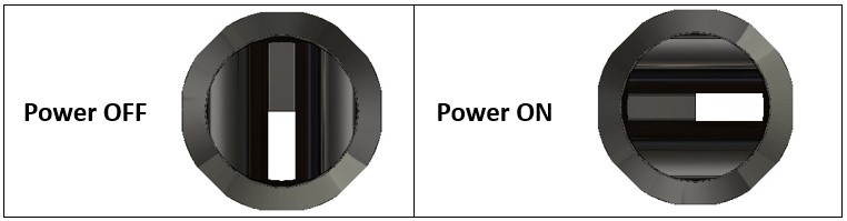
When the white mark on the switch is towards the engraved power symbol, the K-Cell is on.
Power
The K-Cell is provided with both AC and DC power cables. Power input ratings for each can be found in the K-Cell specification section.
AC power cable
| AC power supply WARNING: |
|---|
| _ The equipment must only be operated with a protective earth connection. In the permanent electrical wiring to the mains socket, a 3 Amp rated energy-isolating device, for example a fuse or circuit breaker capable of providing complete disconnection, must be provided in both the live and neutral phases. _ |
| Modification to the Krucial supplied AC power cable is not advised as it could lead to damage to hardware or a risk of electrocution, during or after installation. A suitable socket should be used to connect the plug (details below). |
| _ Installation of AC sockets for the AC power cable must only be undertaken by an electrician holding the relevant qualifications to undertake electrical installation work in the country of install. _ |
The K-Cell/K-Mote AC cable has an IEC 60309 standard plug (otherwise known as: CEE plug, Commando plug). This can be mated with any brand, where the specification is:
- Single-phase
- 16/20A rating
- 2P+E (other names: P+N+E, 2P3W).
- IP67 recommended (lower IP rated variants are compatible).
- Where AC supply is 100-130V, Key: 4h, indicated by a YELLOW socket/plug
- Where AC supply is 200-250V, Key: 6h, indicated by a BLUE socket/plug
K-Mote-AC-power-cable

The AC power cable supplied is 5m length. Using an in-line connecting socket, the AC cable can be extended, allowing for the K-Cell to be positioned much further from the AC power source.
DC power cable

The K-Cell/KMote DC cable comes as a flying lead, to be wired up to a suitable power supply on the installation. The cores are identified as DC+ with red heat shrink, and DC- without. The cores are also numbered along their entire length, so if the cable needs to be shortened the core functions can be identified as:
| DC cable core number | Function |
|---|---|
| 1 | DC + |
| 2 | DC + |
| 3 | DC - |
| 4 | DC - |
The DC power cable supplied is 5m length.
It is not recommended to position the K-Cell much further from a power source due to losses that will be experienced in the cable. If this is required, use 4x 1.5mm2/16AWG cores of a high-quality cable/wire (similar to that used for the supplied flying lead), and junction with a waterproof connector or junction box. The longer the extension, the bigger the losses, and so the more powerful (above specified) the DC power supply will need to be.
Power cable connection
- Fit connector onto K-Cell socket and push into place.
- Twist locking ring to the right so that markers align.

- Connect other end to power source, with power source isolated.
- Secure cables to fixed objects, allowing slack at each end for strain relief.
- Switch on power source.